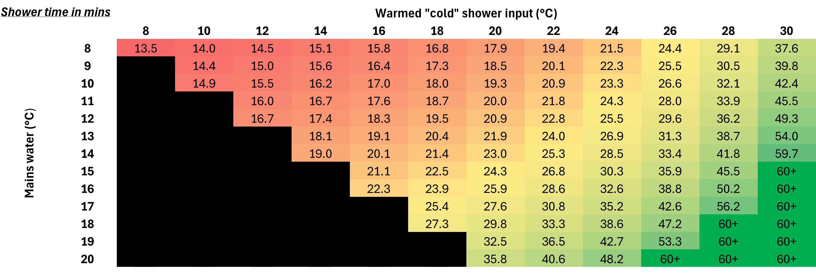
UPDATE 29-AUG-2024: You can try out my calculator for yourself here. This also includes an input to see the effect of heat recovery on your waste shower water, such as when using something like Recoup. Thanks James for the suggestion. A grid of these heat recovery results are added at the bottom of the page - they are quite impressive and could be a great option if you are simultaneously renovating a bathroom.
I have a relatively standard 3-bed semi detached house, but am struggling to find an Air Source Heat Pump system that works for me. This new Heat Geek mini store might be the answer, but I wanted to run the numbers for my own situation before committing.
I am trying to replace my combi boiler from the last millenium with a new heat pump. I discovered that I would need noise planning permission (perhaps a discussion for another day) but also that there was no good place for a hot water tank anywhere. I have an old airing cupboard and loft, so is hardly a tiny flat - highlighting the level of infrastructure needed to enable a heat pump retrofit.
Around this time I watched this video from Heat Geek announcing a new product they claim can deliver domestic hot water in a vastly reduced size as compared to standard water tanks, with a greatly simplified system design too:
This product officially launched last week, with relatively limited performance data available. Someone might be taking the plunge effectively blind, but despite being an ideal early adopter, I am going to need more evidence! [Edit: As I was writing this, some people are now starting to test it. Also it looks like Heat Geek does publish a sizing tool for their own installers… but that’s no fun if you can’t access it!]
My day job is spent breaking down or building new tech - let’s see if we can work this out from first principles. It also gives a good excuse to bounce around a bit of fundamental thermodynamics… but click here to skip to the analysis!
Tangent - oversimplification and obfuscation
Something that massively frustrates me as an (I would like to think) a relatively informed consumer is the mess of information currently out there for heat pumps. All parties have their sins:
- manufacturers being able to quote their machine specification in a myriad of ways,
- installers and plumber running off “anecdata” and rules of thumb to size equipment (the statement old houses can’t have heat pumps needs many caveats - it’s simply a maths problem to be solved, and clearly has been messed up in the past. Once sized, it may be clear the system is cost prohibitive, which I won’t disagree with). This is something that is improving, particularly via organisations like Heat Geek
- and even enthusiasts online posting about their own system involves plenty of acronyms and their own brand of anecdata - their own heat pump performance, sometimes with incorrect explanations attached!
Heating water - the fundamentals
This following section might be labouring the point a bit to most of those reading this - but it is crucial to understanding the pros and cons of what follows.
Lets remind ourselves about the difference between energy and power. Energy is “the ability to do work” and is normally measured in Joules, J. Now for our purposes here we’re only really looking at a heating system for humans to be comfortable, and heat is a byproduct of storing energy in matter. In theory we could build a system to “do work” (e.g. turn into mechanical motion) as our heat energy is lost from our house, but that would be quite hard for not much gain. Incidentally a heat pump is the embodiment of the reverse of this concept, where work is inputted (via an electrical pump) to move heat from a colder area into a hotter area.
Power is the rate of energy transfer. So if I deliver 10kJ of energy in 5s, the power delivery (if we assume it is constant):
\[P = \frac{E}{t} = \frac{10kJ}{5s} = 2 kW\]
And we use the unit W, Watts to denote power. Also, just to confuse people, in heating and power generation the unit kWh is often used for energy. So what’s happening here is a Joule is being divided by seconds to get Watts, then multiplied by hours to cancel out that division, but not going back to Joules!
\[1kWh = 1kW \times 1h =\frac {1kJ}{1\cancel{s}} \times 3600 \cancel{s} = 3600kJ\]
The other essential equation to be aware of is how to translate energy into water temperature. Luckily this is quite straightforward with a single fluid (water) not undergoing a phase change (hopefully!) like boiling.
For a given energy input, Q, we can calculate the temperature rise using
\[Q=mc\Delta T\]
Where m is the mass of fluid (water), c is the specific heat capacity of water, and ΔT is the change in temperature (either in °C or K).
And if we have a power input, recall we divide the left hand side by time, so we can divide either m or ΔT on the right hand side by time. I am going to use a dot above a quantity to show it is “per unit time”.
This gives
\(\dot{Q} = \dot{m} c \Delta T\) for the power delivery to a given flow rate of water, e.g. water flowing past a heating element, this will give the temperature rise across that element
Or
\(\dot{Q} = m c \dot{(\Delta T)} \equiv m c \frac{dT}{dt}\) which will give the rate of temperature increase in a fixed mass of water.
For situations like these it is always useful to keep an eye on the units in your equations to ensure both consistency and insight into what the equation is actually solving for.
Why we use hot water tanks
A hot water tank historically was able to take a low power source, run it for a long period of time, and store up a large amount of energy (in the form of hot water). That hot water can be used up faster than it took to generate, effectively creating a large power output. Older houses might have a vented hot water tank that fills up and depletes. The massive drawback with this is that things could crawl down the vent and end up in your water… (hence the long held hesitation to not drink from the hot water tap).
When the required power output (say to produce a hot shower, when mains water is at 10°C) can be delivered by your heating system, a tank is redundant - like with a combi boiler or electric shower where mains water is heated directly. This simplifies the plumbing and saves space. Therefore for the last couple of decades hot water tanks have been getting ripped out.
Now, with heat pumps getting installed, hot water tanks are back. These days they are unvented cylinders (requiring expansion vessels to accommodate water expanding as it heats), but fundamentally achieve the same effect. Taking a shower is one of the highest power demands you can place on your heating system. If the heat pump were sized to meet this power demand it would (normally) be much, much larger than if it needs to meet your radiator demand, and accept it can be used to slowly heat up your hot water tank.
I orginally wrote more here explaining the balance between hot water and heating when sizing your heat pump, demonstrating this. However there’s plenty of information about this online if you’d like more detail.
Some simple examples
Let’s create a simple hot water delivery model and layer on complexity to compare how the mini store might perform. We’re going to connect all of these to a monobloc heat pump (that means the whole unit is outside - with the only flows going in and out are cold and hot water, we don’t need to concern ourselves with the refrigerant loop) on one side, and a shower on the other side.
A useful trick is to draw “control volumes” around different parts of the system, and note all energy flows (normally in the form of a fluid - higher temperature is higher energy) in and out of these volumes. If you know no energy is being stored within the box (for example if we box off the heat pump) then the energy flows must balance - out must equal in. If we know there are unbalanced energy flows, then energy is being stored in the volume, such as is in the tank water.
In the image below:
- We is electrical power in
- Qa is heat extracted from the air
- h is is the “enthalpy” of the fluid flows. This is a measure of the energy contained within the fluid. Four our purposes here the easiest way is only ever to think about differences in enthalpy. So hhw - hcw is the energy imparted to the hot radiator water
- QHX is the heat transferred by the heat exchanger coil. Sometimes this heat flow is equal to the full output of the heat pump, but can be lower than the heat pump output in certain situations. We’ll explore below when this becomes the rate limiting step in the reheat of the system.
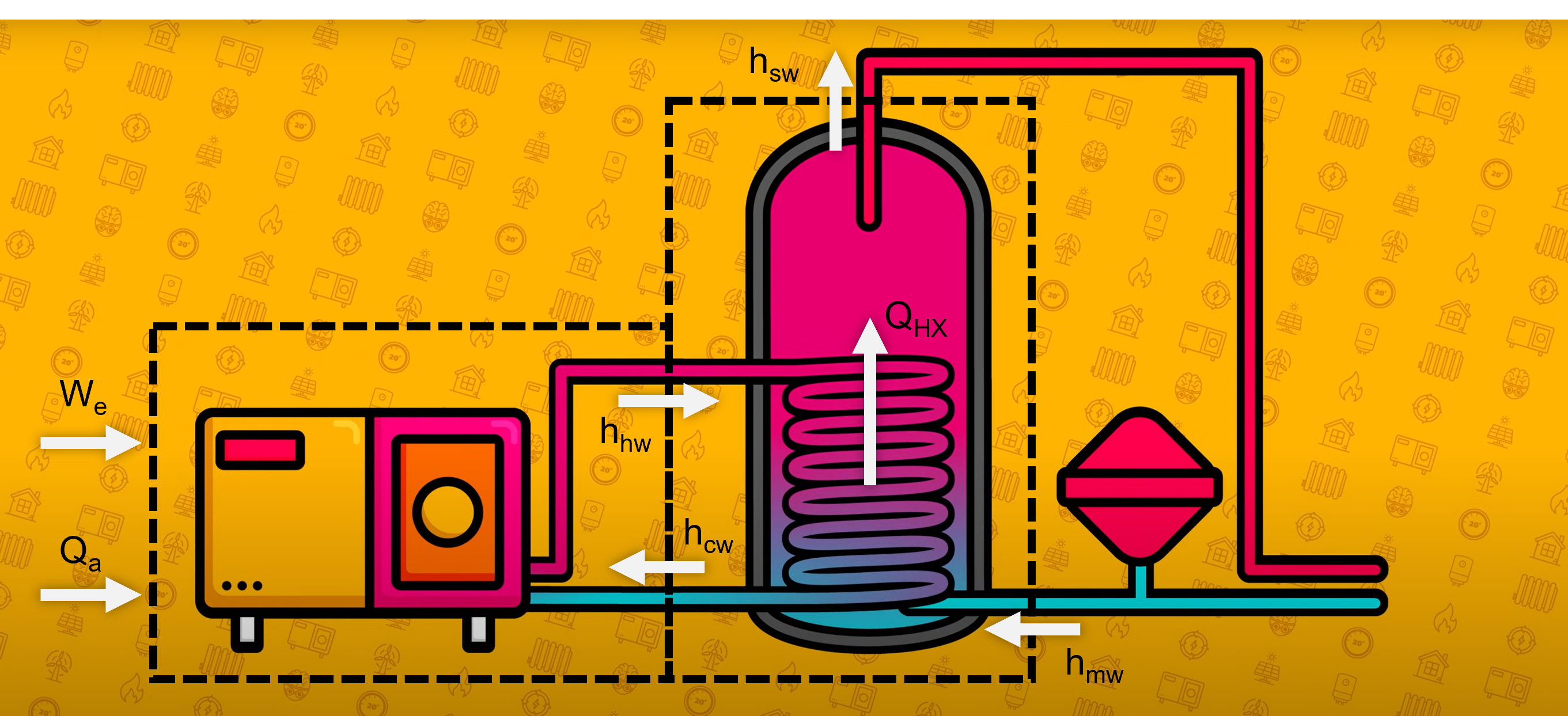 Image - Adapted from Heat Geek
I measured my shower at 9.5L/min - this seems like a very comfortable flow, not optimised with restrictors or aerators. As we’ll see in a minute, decreasing your demand flow rate is one of the biggest improvements you can make for your mini-store…
Vented cylinder
This is the most simple model as there is just hot water at one temperature that gets used up.
Lets assume I have a tank of 200 L, and a target temperature of 55°C. This shouldn’t impact the COP of the heat pump too much, it should be able to deliver heat all below 60°C. Also we’re going to ignore Legionella for now!
I turn my shower on. To get 9.5 L of 40°C water from 10°C cold and 55°C hot, only 2/3 needs to come from my tank. I used this equation as a weighted average, solving for the hot water fraction required x:
\[xT_{hot} + (1-x)T_{cold} = T_{shower}\]
As such the tank is drained in 39.5 minutes.
A well mixed, unvented cylinder
But these days cylinders are unvented as mentioned earlier. What impact does this have?
Well the lost volume needs to be replenished by cold water. Lets assume the tank is mixed up by this outflow / inflow of water and has the same temperature throughout the whole water volume:
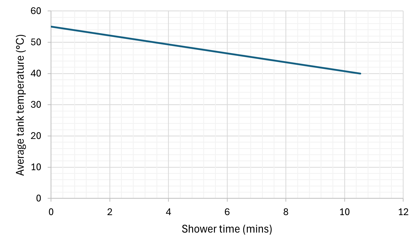
10 minutes! So that’s a bit disappointing. We can no longer generate a hot shower once the tank drops below 40°C. The reheat time will be a lot faster (starting a whole tank from 40°C rather than 10°C) but still feels like a step back. We can make a minor improvement if 5kW heating is applied to the tank (as mentioned before we can’t expect large input powers for traditional cylinders):
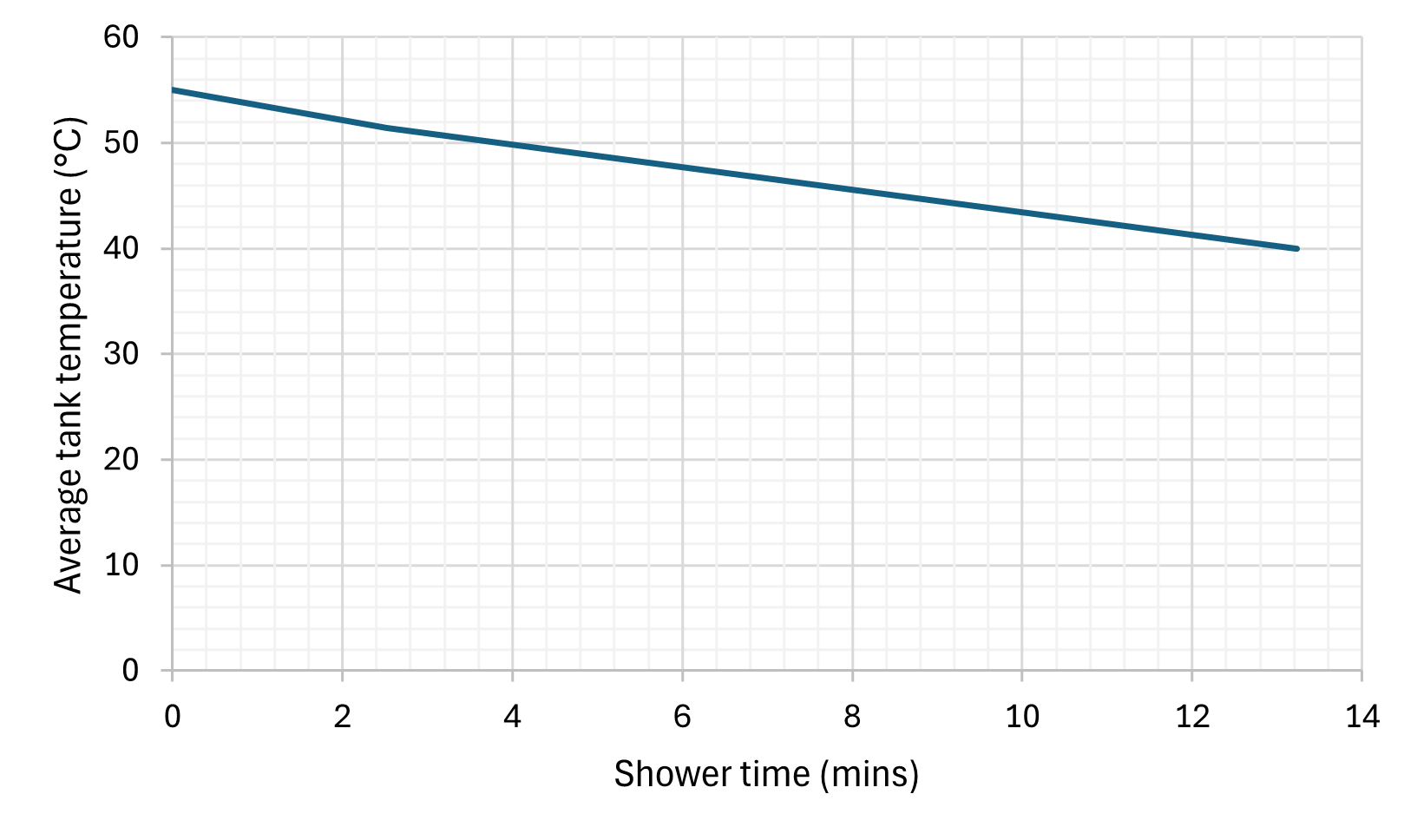
But also shows why some cylinders might be kept at ~70°C to increase this shower time.
An aside about grades of heat and entropy:
- Not all energy is equal. Because heat always flows from higher temperatures to lower temperatures, we call heat at a higher temperature “high grade heat”. If it is hotter than most things in the system, it is valuable because its energy can be transferred easily wherever we want (without a heat pump). Low grade heat on the other hand can not be readily utilised in the same way.
- Therefore for our heating system the easy / lazy thing to do would be to let entropy grow (entropy always increases - this is a measure of disorder, or in our case how mixed everything is - a separated hot tank and cold tank is more ordered than one big mixed warm tank). This would result in a tank of a single even temeprature throughout. However as soon as that tank reaches ~40°C, our shower starts feeling a bit chilly.
- We don’t want to waste our high grade heat on warming up cold water, that could equally be done by our low grade heat.
- Being cognisant of our grades of heat, if we can keep our tank from being mixed, we can employ a few tricks. First we can get closer to our vented tank behaviour - this is exactly what Mixergy, or the Heat Geek super cylinder attempts to achieve.
- Secondly, the cooler end of the tank is still hotter than incoming mains water. This will prove important for our mini store.
So by employing stratification we can theoretically match the vented cylinder capacity if well designed.
Coils, coils, coils
How long does the tank take to reheat (i.e. when can we have another shower?) That depends on quite a few more variables. The coil in the tank that transfers heat from the heat pump hot water loop into the tank water is not big (that would add cost - and why bother, it’s easier to make the tank bigger and spend a long time reheating) and the heating time also depends on the temperature in that loop.
Let us treat the HP as a “black box” that takes electricity in and heats water. This, at normal hot water temperatures, can be done at the full capacity of the heat pump (e.g. 10 kW). At the other end we have effectively a heat exchanger.
Heat exchangers can also be modelled by
\[Q = UA \Delta T\]
The secret sauce is in quantifying U. That is a whole field in of itself, but things that increase U which feature in this analysis:
- Flowing liquids are better, this promotes mixing avoiding the scenario where only the liquid near the solid boundary transfers heat, rather than the whole volume. Faster flowing liquids have a higher Reynolds number, and will become turbulent, further increasing mixing
- Material choice, copper is very conductive, but more expensive
- Shape and layout of the coil. Some of this is factored in with the surface area, but the arrangement will also have an impact. Furthermore a “counter-flow” arrangement is able to transfer more heat by using the already quite cool “hot” side to heat the incoming cold stream. Throughout the heat exchanger the hot side is always slightly above the cold side (water to water heat exchangers if well designed can maintain a ~5°C temperature difference).
When ΔT is small the heat transfer from the coil into the tank may be smaller than the output of the heat pump. To increase power input to the tank we could
- Increase the HX U-value
- Increase the HX area
- Increase ΔT
- When the tank is cold, ΔT will be bigger and the heat pump can work at its optimal temperature range (generally 45-55°C) without worrying about the HX limitations
- When the tank is approaching its target temperature ΔT will reduce. We can either accept the reduction in heat power into the tank, or raise the HP flow temperature - negatively affecting its COP.
The Heat Geek super cylinder video does a good job of qualitatively describing this.
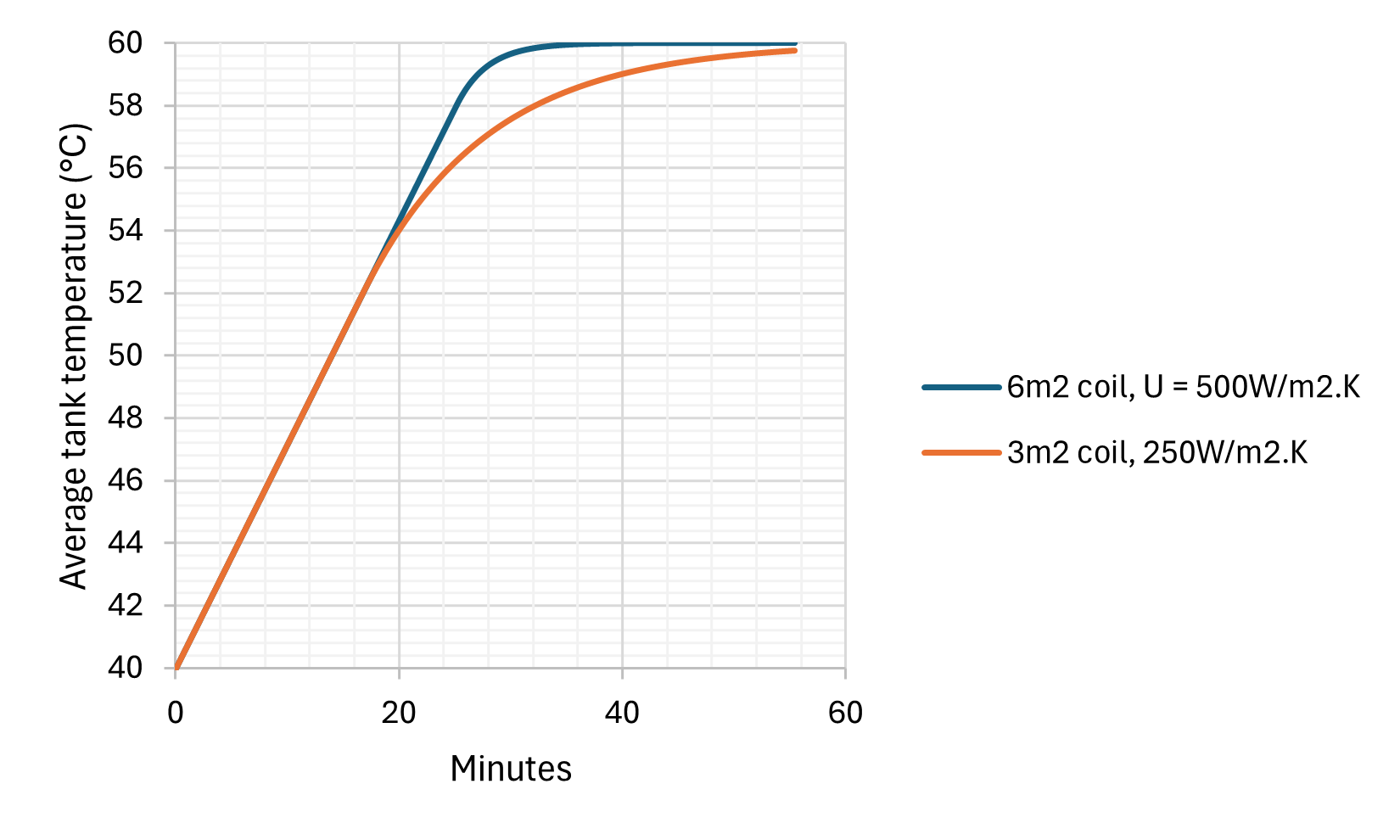
A simple demonstration of this is below comparing lower and higher performance coil in a 200L tank being heated by a 10kW source. (This quick calculation assumes the tank is mixed, which for a large tank being heated is not a bad assumption due to the natural convection currents that may be set up. Although through most of it we are limited by the 10kW heat source, a cleverly stratified tank may create useable 60°C water sooner than a mixed tank.)
The Mini-store
After plenty of preamble we’re finally ready to take a good look at the mini store. The available data I have found comes exclusively from the tank specifications and heat Geek’s own explanation video.
The explanation of this system is perhaps simpler than the previous ones - the “radiator water” flows from the heat pump into the tank. When hot water is requested, mains cold water flows through the coil and is heated from this thermal store. Within a couple of minutes the heat pump should detect the store temperature is dropping and will switch on to try to maintain the tank temperature. The store alone is not very big and the system does quite heavily rely on concurrent heat input from the heat pump. Because the output hot water must be heated on demand it relies heavily on a large high performance coil, which is likely why no one has widely commercialised such a system yet (in the UK…)
 Image - Heat Geek
I’m going to assume a 7 kW Areotherm Plus heat pump (matching the video) - note this can deliver up to 10 or 11 kW outside of extreme cold conditions (going back to my earlier point around confusing specifications). The model is built such that the tank is assumed to have a linear temperature gradient at all times, cooling the bottom first, and then depleting the top temperature when the bottom reaches the inputted heat exchanger “pinch” (5°C difference as a minimum to ensure heat can flow).
The datasheet indicates their specifications are calculated with the heat pump coming online 150 seconds after the shower starts. In reality this is a 3°C hysteresis trigger (i.e. the pump triggers when 3°C below target) but will depend on heat pump circuit volume, so I have kept the time delay.
Having built the model, the first step is to validate it. The video unfortunately did show some information, but left out lots of specifics. This, I assume, was so not to over-promise on performance.
The graph flashed up at 13:30 is very useful however. Firstly we can work out which model he is using by looking at the preheating portion (blue annotations):
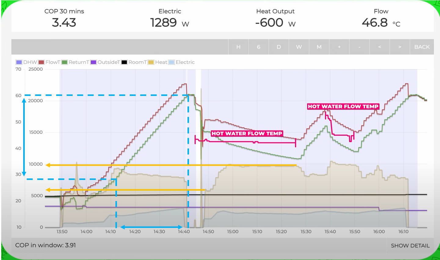
\[Q = Pt = mc\Delta T \\
\sim 8kW \times 30 min = m \times 4.184 kJ/kg.K \times 32 K\]
Giving m = 107.5 L. So he is using the FAT store (110 L).
We can also roughly infer the tank temperature at the top (the flow from the heat pump) and the bottom of the tank (the return flow to the heat pump).
Finally, the other important parameter is the heat exchanger. We know the surface area, but the U value is going to be a pretty big guess. Shell and tube heat exchangers are in the region of 350 -1500, but this lacks fast tank side fluid flow, which will limit heat transfer. We can pick 500 W/m2.K as a baseline, assuming all other features are well optimised for heat transfer.
Running the simulation using the following logic
- The tank is initialised at its target temperature.
- Flow out of the tank is always
X°C lower than the top of the tank temperature, where X is an inputted “pinch” temperature”
- Flow is requested. The temperature of hot and cold water sets the ratio required, and the outflow from the tank.
- Water is heated from cold to the exit flow temperature. This power input Q=mcdeltaT, is mirrored by a power out of the water vessel. This power out leads to an average temperature reduction. However we initially keep the top of the tank constant and realise the temperature drop by reducing the tank bottom temperature.
- After 150s the heat pump kicks in and starts delivering power to the tank. This slows the average temperature reduction.
- HX heat transfer is a function of only U, A, and the temperature differences at either end. Since we have set one end (X, in step 2) and know the incoming mains water temp, we can solve for the limiting case for the lowest temperature in the bottom of the tank, where the heat exchanger heat transfer equals the demand power.
- Eventually the bottom of our tank reaches this limiting temperature (while the top is still at the original temperature). Heat is still being demanded from the tank so the top temperature starts to drop. We need to maintain the output pinch temperature, so the outflow temp also drops. The ratio of hot water also increases to compensate. (Note, if we draw a box around the whole system, it is raising mains water from 10°C to 40°C at a constant flow rate, it doesn’t matter whether it is doing it directly, or mixing hotter water and cold water).
- When the outflow temperature drops below 40°C, it’s game over.
Tangent - power potential
In the video, he mentions the coil being able to deliver 50 kW instantaneously. This aligns well with our model which shows the coil is capable of 55 kW heat transfer at t=0s. Now this is totally academic unless you had huge flow rates that was capable of receiving this heat. I think it is a confusing point for the average person and distracts from the main narrative.
Matching some of the key known parameters in the video:
- Incoming water temp = 16°C - this assume the start of the graph above is the tank starting from cold.
- Tank temperature = 60°C
- HP input power = 10 kW
- Flow as 8.5 L/min (this is quoted in the video)
The model estimates a shower time of 43 minutes. Noting that the heat pump doesn’t appear to reach 10 kW until about 10 mins into the shower, ramping from about 6 kW of heat (orange annotations):
\[\frac{ 8kW \times 10min + 10 kW \times 30 min }{ 40 min} = 9.5 kW\]
We get 39 mins, which is pretty on the money.
We can roughly compare the profile of the HP flow temperature (which feeds into the top of the tank) and the HP return temperature, drawing from the bottom. This suggests the rigid fixing of top and bottom temperatures needs smoothing somewhat and bringing closer to the average, but the profile looks roughly applicable.

Lets construct a “likely worst case” using the same tank in my home. With a shower flow of 9.5 L, an incoming mains water temperature of 8°C (we tan use table J1 in the Standard Assessment Proceedure), and the same heat pump (producing ~9.5 kW) but a lower tank temperature of 55°C for hopefully slightly improved COP.
This would result in me getting a 13.5 minute shower, with tank recharge time of 12 19 mins. [edit: 12 minutes to reheat from 40, but we can take the average temperature lower than this.] This, I think, is just about acceptable even in the middle of winter! We can go further - lets se how this shower time varies as we adjust each input independantly (i.e. all the others remain constant).
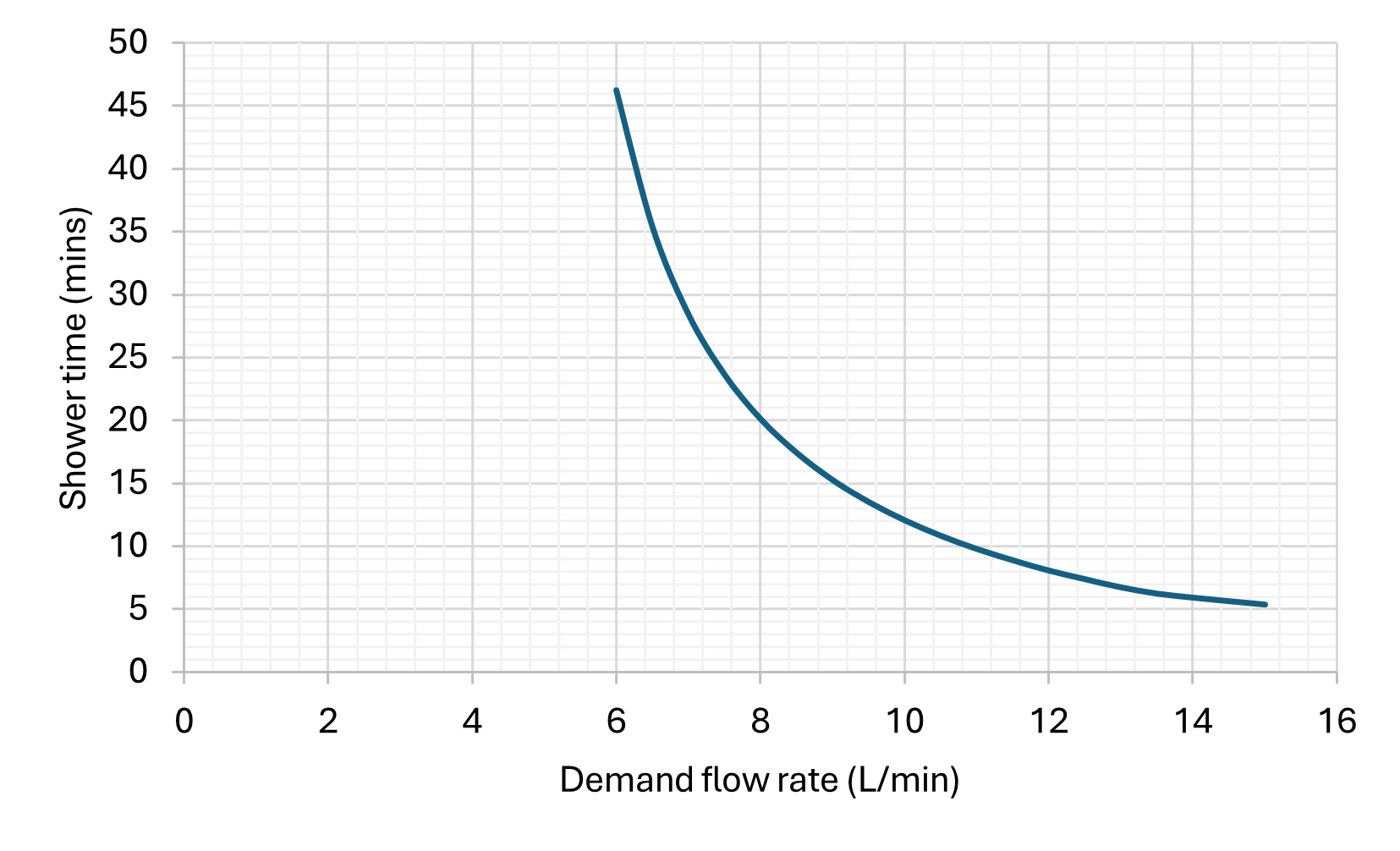
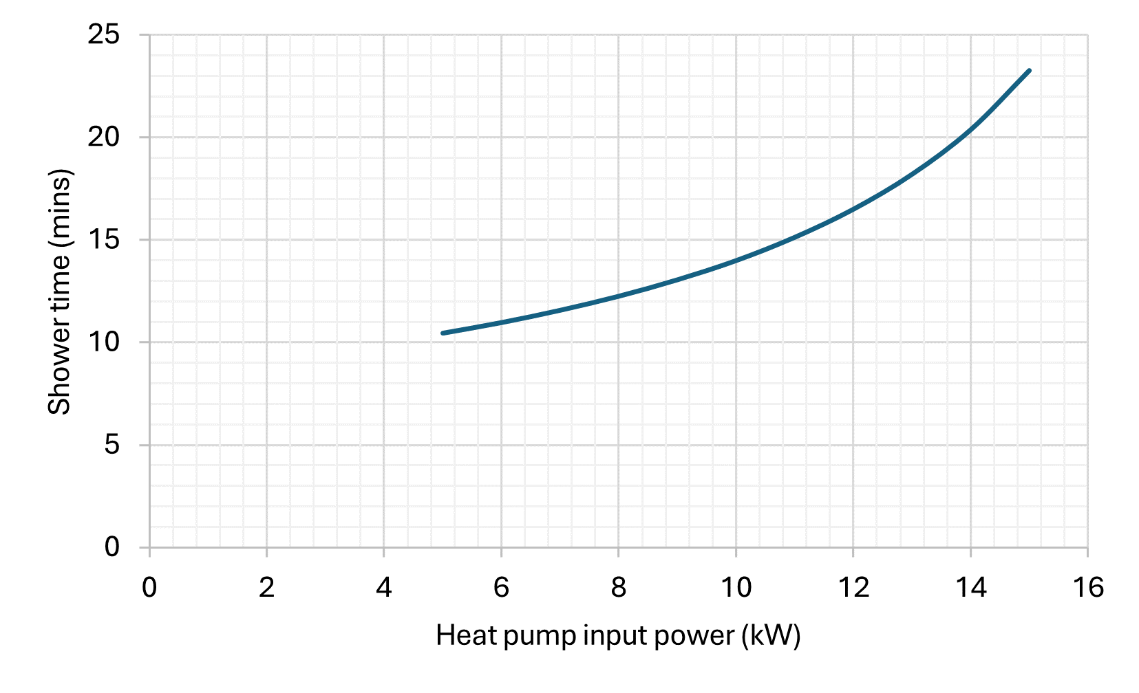
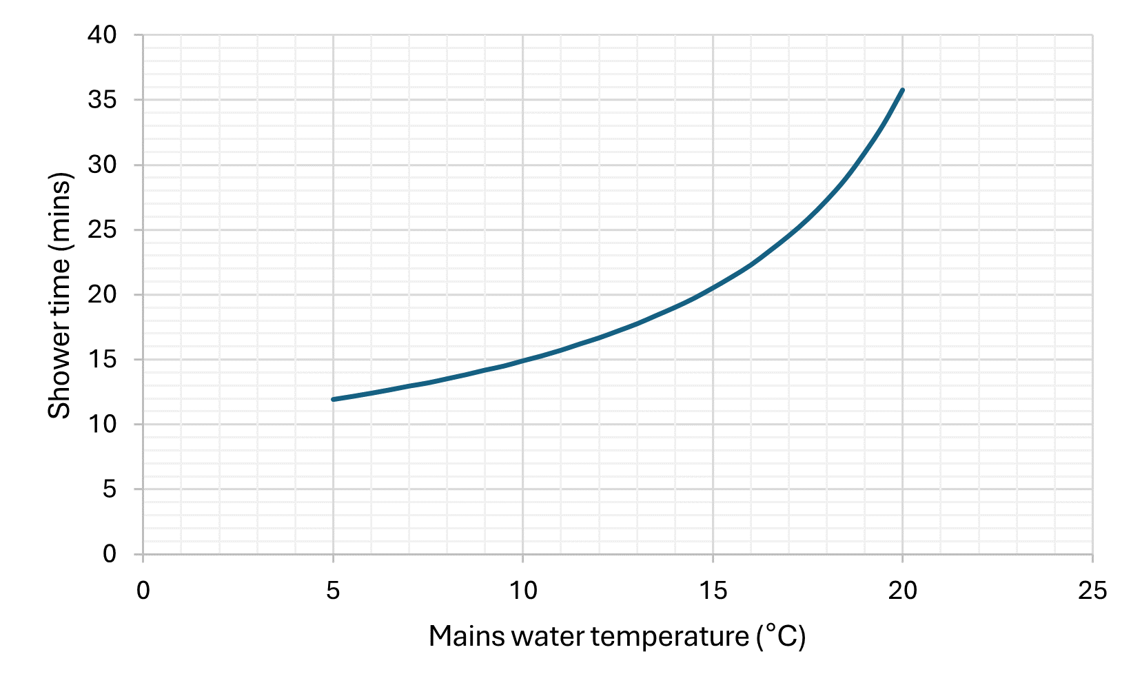
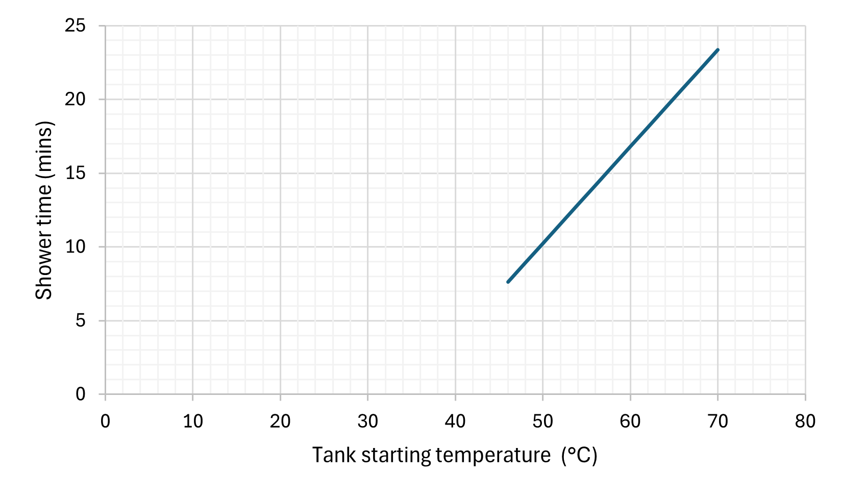
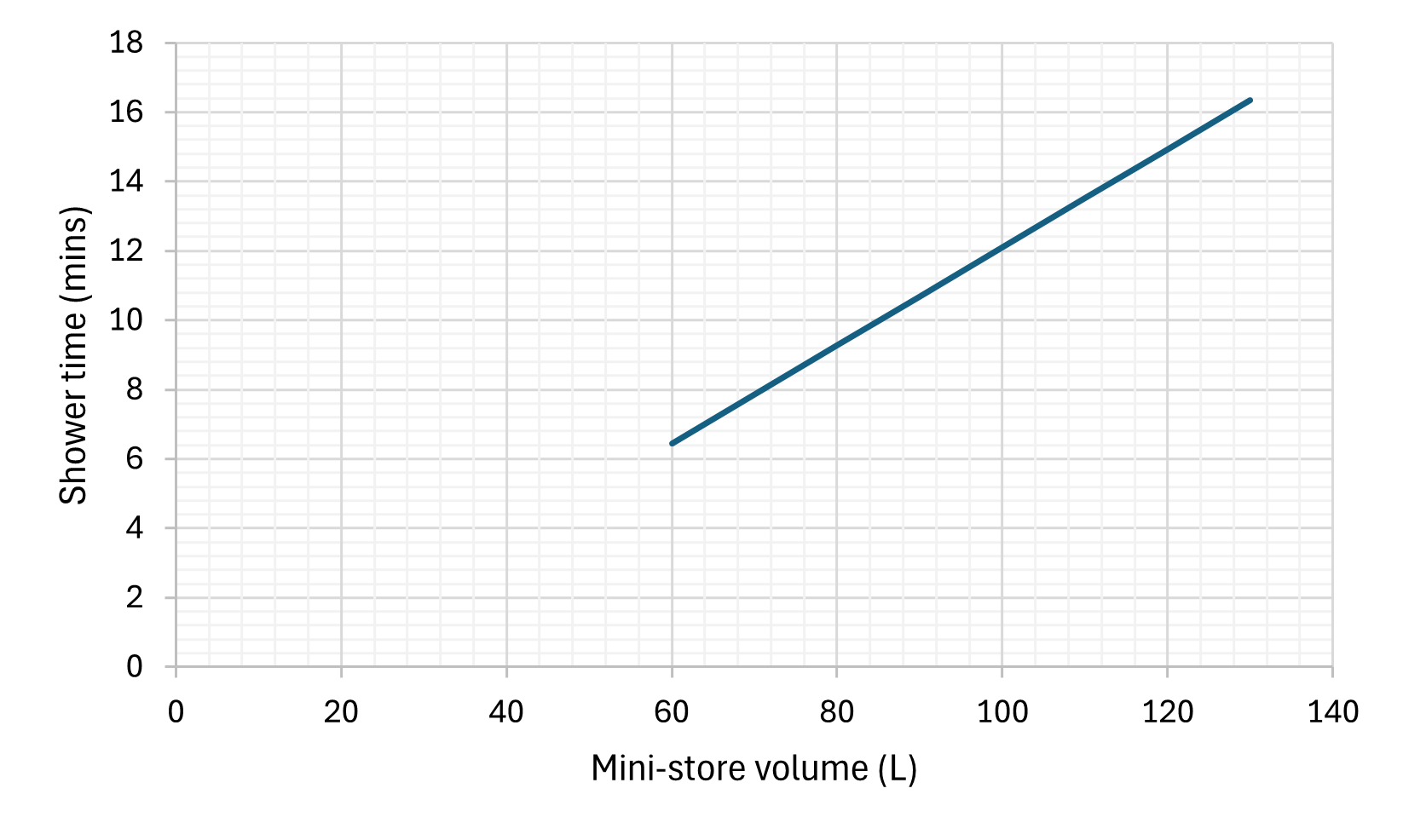
A quick sensitivity analysis on the estimated parameters shows their contribution to the final result (and therefore relative error) is low as compared to other inputs.
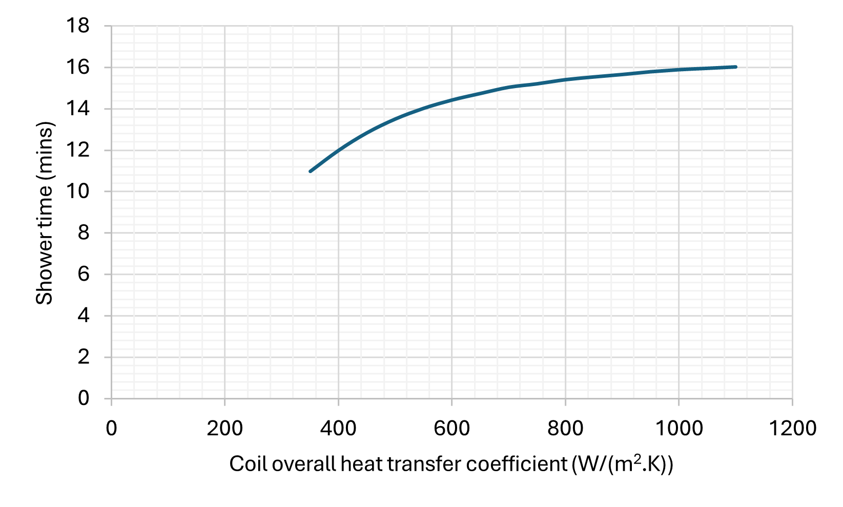
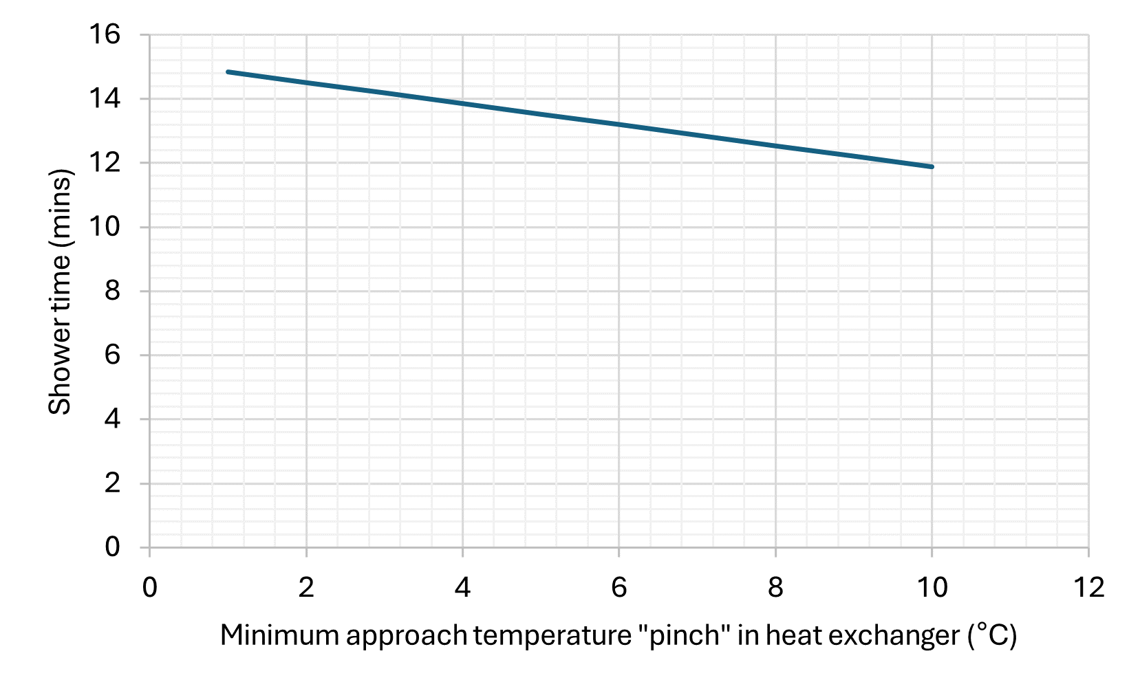
As we can see, limiting the flow rate would have a particularly signifcant benefit. Also it is useful to see where the various models / volumes sit in comparison to each other.
Overall I can certainly see this making a reasonable impact in the heat pump market. So many terraced homes have the main colds water in, combi boiler and hot water output to the rest of the house all in the same corner of the home. Not only is this smaller, it’s able to squeeze in that same corner. Heat pump installs can still easily exceed £5k (even with the £7.5k grant) due to the labour effort in reconfiguring house plumbing, but I could see a heat pump & mini-store being entirely covered by the grant in the near future. The only remaining question will be if people are prepared to take the hit on hot water volume.
I hope to share a copy of my calcuations spreadsheet shortly so you can see for yourself!
UPDATE 29-AUG-2024 continued: I’ve shared the link at the top of the page, and here is the grid of shower times as we vary the temperature of the mains water (flowing through the Mini-store) and the “cold” water flowing into the shower mixer. I have used quotes there as the cold water can no be preheated using the warm water that’s just flowing out the drain. Having pre-warmed cold water means a smaller proportion needs to come from the hot side, lowering demand on the Mini-store. This has a very similar effect to just lowering the shower flow rate. Could be well worthwhile depending on what the heat recovery products claim!